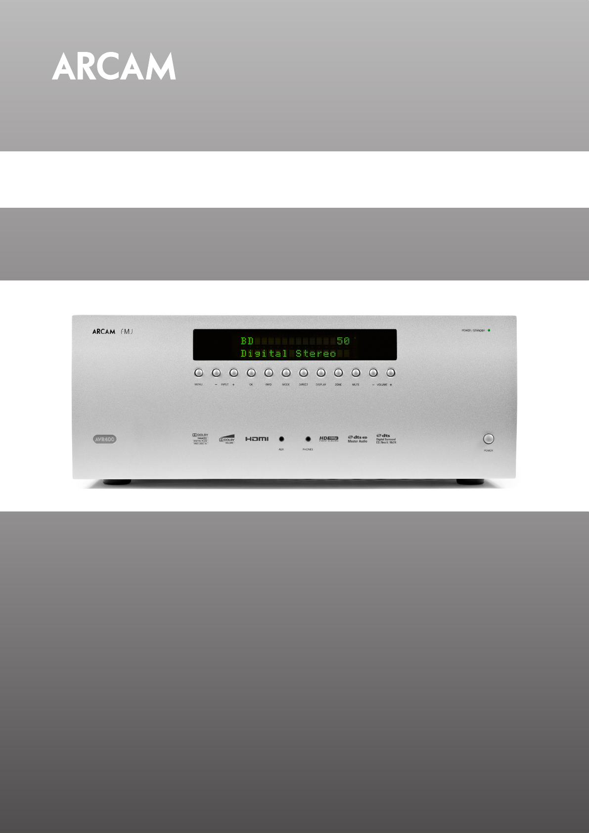
Arcam AVR400 Manuel d'utilisateur
Naviguer en ligne ou télécharger Manuel d'utilisateur pour Amplificateurs audio Arcam AVR400. AVR400 Service Manual Issue 1 Manuel d'utilisatio
- Page / 34
- Table des matières
- MARQUE LIVRES
- AVR400 MAIN ASSEMBLY 2
- AVR400 RS232 board 15
- AVR400 Analogue Video Board 19
- 2326SCMZ 20
- SCHEMATIC DIAGRAM 20
- CUP12328Z 25
- CUP12329-1 30
- L.K.M L.J.H 30
- 10.11.18 10.11.18 10.11.18 31
- VIDEO PART 32
- POWER PART 33
- RS232 PART 33
- SCREW MARK 34
Résumé du contenu
AVR400 Service Manual Issue 1
It communicates with the Input Board via CN101 and a 31 way ribbon cable. Other connectors comprise CN94 which connects to two secondaries of the main
the same manner as described above for RL902) then the L front input is routed to the low noise micro-phone amplier IC903. This operates as two casca
IC101 has one 8 channel variable level output bus labelled VOL01 through to VOL08. Capacitors C295-8 and C231-4 oat the ground ends of the associated
IC143 is the Cirrus Logic CS42548. It includes an SPDIF receiver, 2 channel ADC and 8 channel DAC. Only one input (pin 43) of the SPDIF receiver is us
IC141 also has two sets of I2S data outputs. DA1 is an 8 channel I2S signal (pins 47, 48, 49 and 51) shown as part of the bus DA0(04:07). This feeds t
rogating the USB socket and insertion of a clean USB stick containing only the system rmware will initiate a complete recovery automatically.IC164 is
the necessary level shifting. IC73 includes internal charge pumps to convert CMOS logic level inputs to +/-5V RS232 level outputs and +/-25V tolerant
The HDMI input SOC, IC901, is a 144 pin LQFP Analog Devices ADV3014B. This is a 4 into 1 HDMI 1.4a multiplexer and is connected to inputs 4 and 5 (VCR
Q914 and Q915 (on the underside of the PCB) send BYPASS_ON and BYPASS_OFF logic signals from IC906 to the array of 4 x 20-bit non-inverting line drive
AVR400 Analogue Video BoardThis is connected into the rest of the system via the HDMI board using CN301.The circuitry is shown on sheet 13 of the sche
231ITEM NO.PART No.DESCRIPTIONQTY1TGP3523 / TGP3524FASCIA ASSEMBLY BLACK / SILVER12TGP3526 / TGP3527COVER BLACK / SILVER13HA4V06STORX SCREW M4 x 64805
152326SCMZAVR400(FRONT)J.I.HB12345DCBA6CDAAPPROVECHECKDESIGN DRAWING NO11MODELSHEET1SCHEMATIC DIAGRAMREVISION1234567MPFROM POWER TRANSVFD_CSVFD_CLKVFD
6 1510.11.16AVR400S.KB12345DCBA6CDAAPPROVECHECKDESIGN DRAWING NOMODELSHEETSCHEMATIC DIAGRAMREVISION1234567HP DET+5VGNDDDC DATADDC CLKNCCE REMOTECK-D1
15710.11.16AVR400S.KB12345DCBA6CDAAPPROVECHECKDESIGN DRAWING NOMODELSHEETSCHEMATIC DIAGRAMREVISION1234567SBL/SBRSL/SRSUB/CENFL/FRI2S3I2S2I2S1I2S0In ca
158AVR40010.03.30S.KSCALERB12345DCBA6CDAAPPROVECHECKDESIGN DRAWING NOMODELSHEETSCHEMATIC DIAGRAMREVISION1234567RGB 10BIT INPUT8BIT RGB INPUT*GPROBEA15
HD(30MHZ) MODE : HIGHSD(13.5MHZ) MODE : LOWCLK1S1:HIGHS1:LOWICLK2*ICLKCLOCK DOUBLER(13.5M*2=27M)9 1510.11.16AVR4007654321REVISIONSCHEMATIC DIAGRAMSHEE
151010.11.16AVR400S.KPOWER&CONNECTORB12345DCBA6CDAAPPROVECHECKDESIGN DRAWING NOMODELSHEETSCHEMATIC DIAGRAMREVISION1234567TO VIDEODC/DC REGUALTORTO
123ITEM NO.PART No.DESCRIPTIONQTY1TGP3539TRANSFORMER - POWER12FAN 80 x 80 x 25mm23FAN MOUNTING BRACKET28055TOLERANCES UNLESS 0.00±0.10OTHERWISE STATE
M PFLFRSRSLCENSBLSBR11151DAC325 4DCBA7654321REVISIONSCHEMATIC DIAGRAMSHEETAVR400MODEL21DRAWING NODESIGN CHECK APPROVEB(AMP PART)FLCENFRFROM POWER BOAR
M P12151DAC325 4DCBA7654321REVISIONSCHEMATIC DIAGRAMSHEETAVR400MODEL222329SCMZDRAWING NODESIGN CHECK APPROVEB(AMP PART)SLSRSBLSBRFROM AC INLETTO SWITC
3131510.11.171AVR4002330SCDZ(VIDEO)L.J.YB12345DCBA6CDAAPPROVECHECKDESIGN DRAWING NOMODELSHEETSCHEMATIC DIAGRAMREVISION1234567I2C BUS FORMATS(1BIT) SLA
21410.11.17315AVR4002330SCDZ7654321REVISIONSCHEMATIC DIAGRAMSHEETMODELDRAWING NODESIGN CHECK APPROVEADC6ABCD5 4 3 2 1BL.J.Y(VIDEO)!!!!!!TXRXFROM INPUT
331515B12345DCBA6CDAAPPROVECHECKDESIGN DRAWING NOMODELSHEETSCHEMATIC DIAGRAMREVISION1234567SCREW MARK10.11.17AVR400L.J.Y10.11.17 10.11.17L.J.H S.H.S(V
14235SOLDERED TOPOWER AMP PCBITEM NO.PART No.DESCRIPTIONQTY1TGP3534CHASSIS ASSY12TGP3535FRONT PCB ASSY13TGP3538POWER AMP PCB ASSY14TGP3525FOOT ASSY45T
14235SOLDERED TOPOWER AMP PCBITEM NO.PART No.DESCRIPTIONQTY1TGP3534CHASSIS ASSY12TGP3535FRONT PCB ASSY13TGP3538POWER AMP PCB ASSY14TGP3525FOOT ASSY45T
AVR400 Power Amplier Circuit DescriptionApart from the power transformer, the power amplier electronics is fully contained on the large double sided
additional feedback further reduces high frequency distortion and crossover distortion within the audio band.These stages are partially decoupled from
1) Any amplier channel pulls current through the SOA_PROTECT line for long enough to charge up capacitors C5871 and then C5872 so that Q5874 turns o
Two secondary windings from the toroidal power transformer are fed in via CN63. Pins 1, 2 and 3 con-nect to a centre-tapped secondary winding used to
Plus de documents pour Amplificateurs audio Arcam AVR400


Produits connexes et manuels pour Amplificateurs audio Arcam AVR400
 (19 pages)
 (52 pages)
 (12 pages)
© 2020, manymanuals.fr. Tous droits réservés | 0.339 s |
 Manymanuals.com
 Manymanuals.de
 Manymanuals.fr
 Manymanuals.it
 Manymanuals.pl
 Manymanuals.cz
 Manymanuals.es
 Manymanuals-pt.com
Commentaires sur ces manuels